
Page 6 - B2B 8 to 13
P. 6
these two wires are connected correctly, otherwise the loco will not go forwards when commanded to do so. The blue wire is a common positive for all the lighting functions. The rest of the function wires, of which only white and yellow are in the standard, are switched negative by the decoder to operate lights. White and yellow are intended for the head and backup lights, and the green, brown and violet, if available, for more light functions. Some decoders offer even more than these colours, too.
Hardwiring a decoder is not difficult. First you must ensure that both motor brush connections are isolated from the locomotive frame and track power. Fortunately, most locos made in the last 10 years or so are already supplied with the motor connections isolated, but you do need to check and take action with older locos such as Athearn Blue- box and any brass with an open-frame motor. Can-motor brass rarely has any issues here. Failure to isolate the motor brushes will mean that the loco won't run, and the decoder may smoke, too. Fortunately most decoder manufacturers and their dealers recognize that this can happen, and have decent warranty programs for replacing decoders that you blow up in installation. Just don't do it too often!
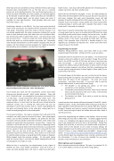
Digitrax DZ143 decoder hardwired to Overland HOn3 K-36 chassis, including plug for headlight and a firebox light. Photo: Mick Moignard
You'll should also check the the locomotive's current draw when choosing your decoder yourself. Most smaller decoders - those sold for Z, N and HO scale - are intended for locomotives of around 0.5 to 1.5 amp draw. O-scale locomotives often draw rather more. The chosen decoder should be able to cope with whatever the loco's maximum draw is. In most cases, the loco will never actually draw the maximum current, but in running the stall-current test you are checking for a worst-case scenario, such as a piece of grit getting into the gears and jamming them, or the valve gear coming apart on a steam loco and getting stuck in the wheel spokes.
This is tested as follows. You need an ammeter that is OK with 12V DC and which can safely read up to around 10 amps. Most cheap digital meters, such as those available at Maplin’s, are perfect for this task. You’ll also need your old DC transformer-controller, and it needs to be capable of coping with the locomotive’s current draw. Connect the ammeter in series with the loco. You can do this by separating chassis from body and using clip leads to the motor terminals, or just place the loco on a piece of track, and include the meter in series with the track power. Then run the loco at full speed with the DC supply, and physically stop the loco wheels turning. Press down on it on the track to stop the wheels turning, or just grab hold of the wheels or flywheel. While stopped, check the ammeter reading. It’s also worth seeing what the current draw is too with the wheels slipping with the loco running against your finger as a stop.
When the loco is running free, you should expect to see a figure of between 0.5 and 1 amp. Stalled, somewhere more like 0.75 to 1.5 amps, and quite possibly quite a bit more in older brass with open-
frame motors. Such locos will benefit greatly from remotoring with a modern can motor, but that is another story.
Add to that an overhead for any lights. If your DC model already has them, they will be included in the test you just did, but if you plan to add more, consider that each extra illumination source will add between 20 and 50 milliamps (0.02 to 0.05 amps) to the whole. So, for example, if your loco draws 1.2 amps stalled, but only 0.4 amps when running normally, it will be safe with a decoder that claims 1 amp steady and 1.5 amp peak, for example.
Next choice is space for the decoder. Brass locos have masses of space in nearly every case I've seen, as do older plastic RTR locos, but some come filled up with metal chassis castings, and can be tricky. I use Blu- tak extensively with such locos to check what space is available - adding a lump to the chassis and putting the body back, and then seeing if the squashed lump of Blu-Tak is decoder-shaped or not. Ingenuity can sometimes be required here. Steam locos often have masses of space in the tender.
Programming your decoder
Whatever fitting method is done, you'll then need to do a little programming of the decoder - setting some CVs, as we saw above.
Actually the only one you have to set is the address. This is because all decoders come set to address 3, and if you don't change this, you'll be back to the old DC issue that all the locos will move at once wen you twist the throttle! I can't here go into details of exactly how to program the address, because which buttons to press varies from DCC system to system. However, I can tell you that this is something you do on your system's program track, in either Paged or Direct mode, if your system offers that choice.
You should always do this before you ever run the loco on the layout, because being able to program, and read back the address is a vital check that the basics of the installation - the track and motor connections - have been done right. If you aren’t able to read the decoder address back, it means one of three things:
The decoder is not getting any power, so the track connections, or loco pickups, are faulty
The decoder cannot detect the motor, which means that the motor may be miswired or that one, or both, of the brushes are connected to the chassis
The decoder has failed. Burn marks or smells are the big giveaway here.
I should mention here another difference between DC and DCC, which I alluded to earlier, On DC, the throttle makes all locos go to the left, or right, regardless of the direction the loco is facing. With DCC, however, forward is forward, and reverse is reverse, Two locos facing each other on DCC track, told to go forward, will collide with each other, which is not the case on DC.
Apart from programming the address in the decoder, there are many other things you may want to fiddle with. I’d always suggest that this is done in a methodical and logical manner, because otherwise it is easy to get oneself lost and more than a bit frustrated. Should that happen, and you’d like to start over, you should be able to perform a factory reset on the decoder to set it back to factory settings. All modern decoders have this ability, and most, but not all do it by setting CV8 to 8. There is a chart available from the NMRA – though a little dated – at http://www.nmra.org/sites/default/files/sr201402_dcc.pdf, and the British region has developed more recently a printed card of this information. It is also, of course also available, for your given decoder, in the manufacturer’s documentation.
What might you want to program?
We’ve already mentioned the address. This goes in a standard CV, CV 1, for a short address, and CVs 17 and 18 for a long address.
