Hand Laid Rail Spiking Update
Construction progress has been slow over the last several weeks due to my new role as Renewals Officer for the British Region NMRA. It is quite a daunting task but I have had great support from John Firth and I am beginning to get the hang of it...!
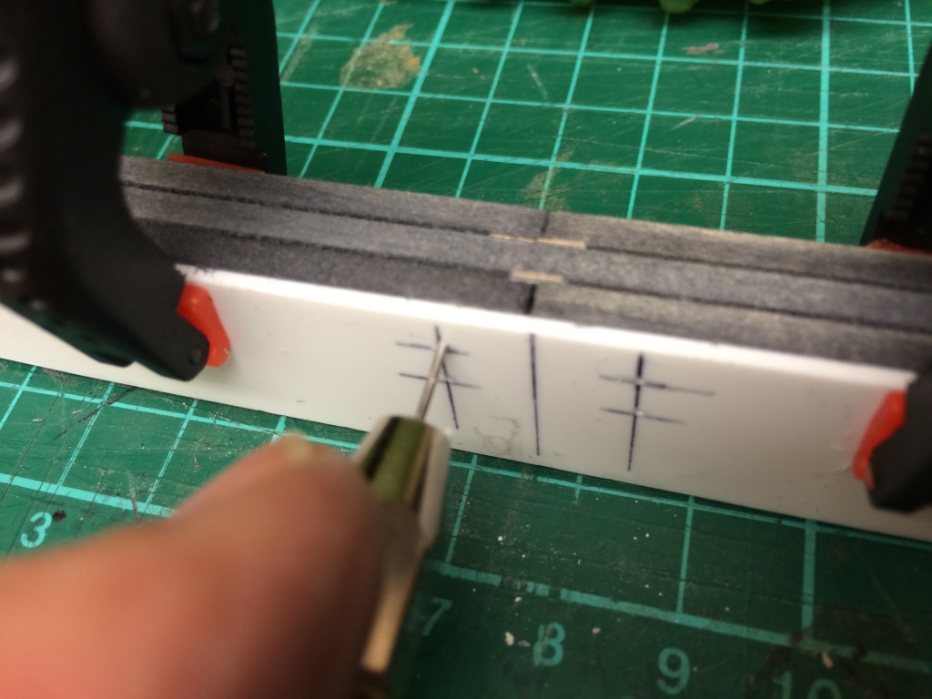
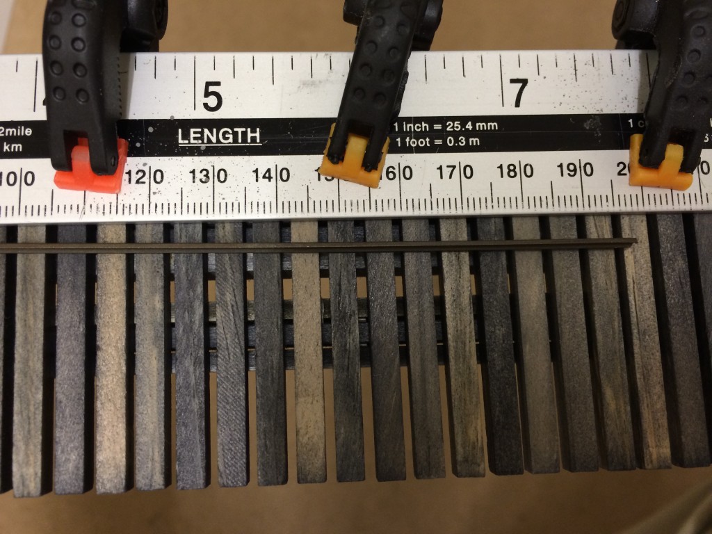
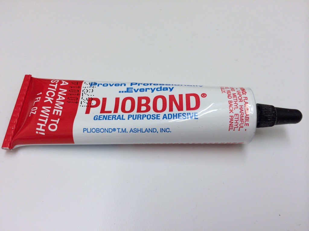
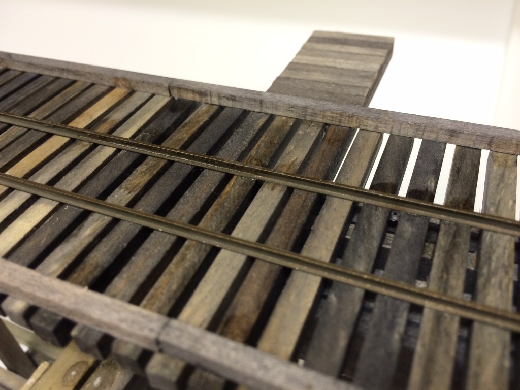
I revisited the "spiking of rail" problem and have concluded that the answer is to use the trusty Pliobond method. Pliobond is a thermally activated adhesive, that is applied to the base of a length of rail and allowed to dry. When heat is applied with a soldering iron the adhesive 'comes to life' and bonds almost instantly to the surface it is applied to.
The manufacturers description of Pliobond states: Pliobond® contact cement is ideally suited for bonding steel, wood, rubber, leather, canvas, aluminum, fiberglass and glass. This adhesive actually gets stronger as it ages and is highly resistant to vibration and expansion/contraction.
I have used this method in the past for handlaying code 70 rail to individual ties, albeit on a solid roadbed or splined roadbed in HO scale and it works very well for laying rail very quickly. Small spikes are then used to secure and align rail at switches.
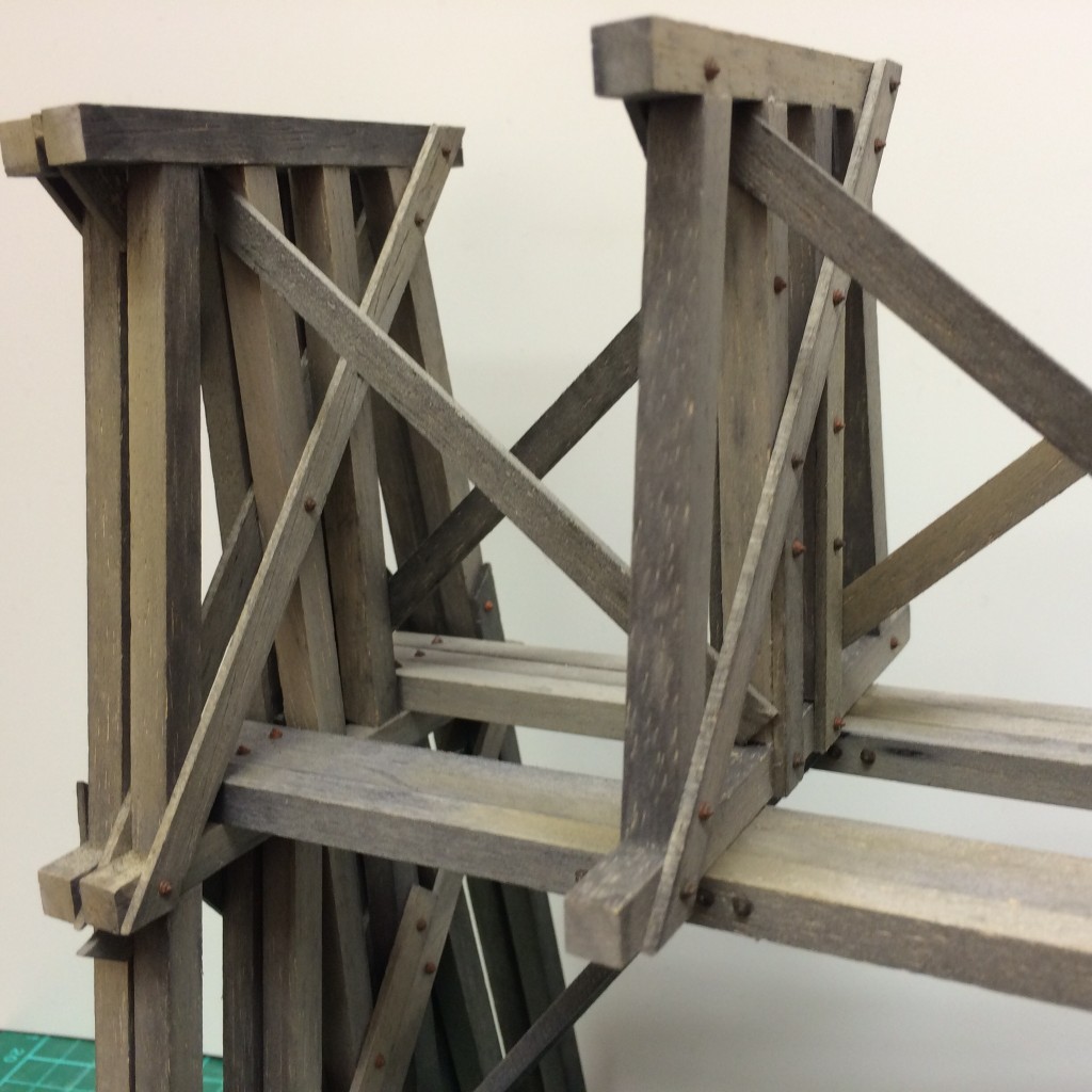
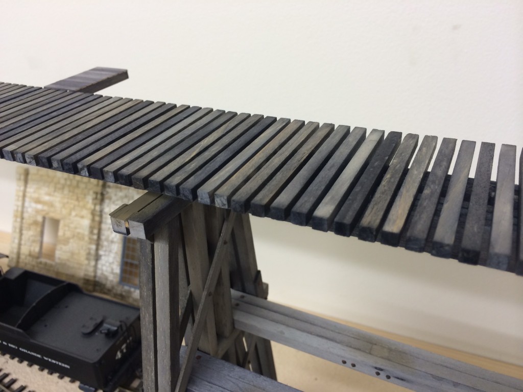
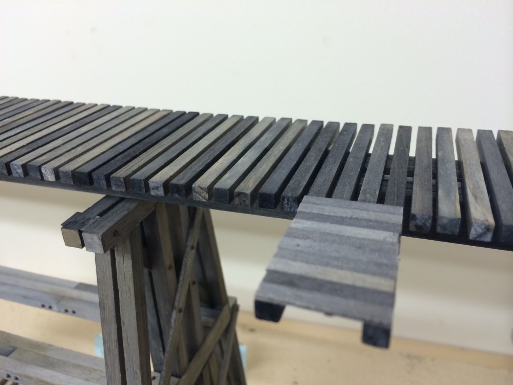
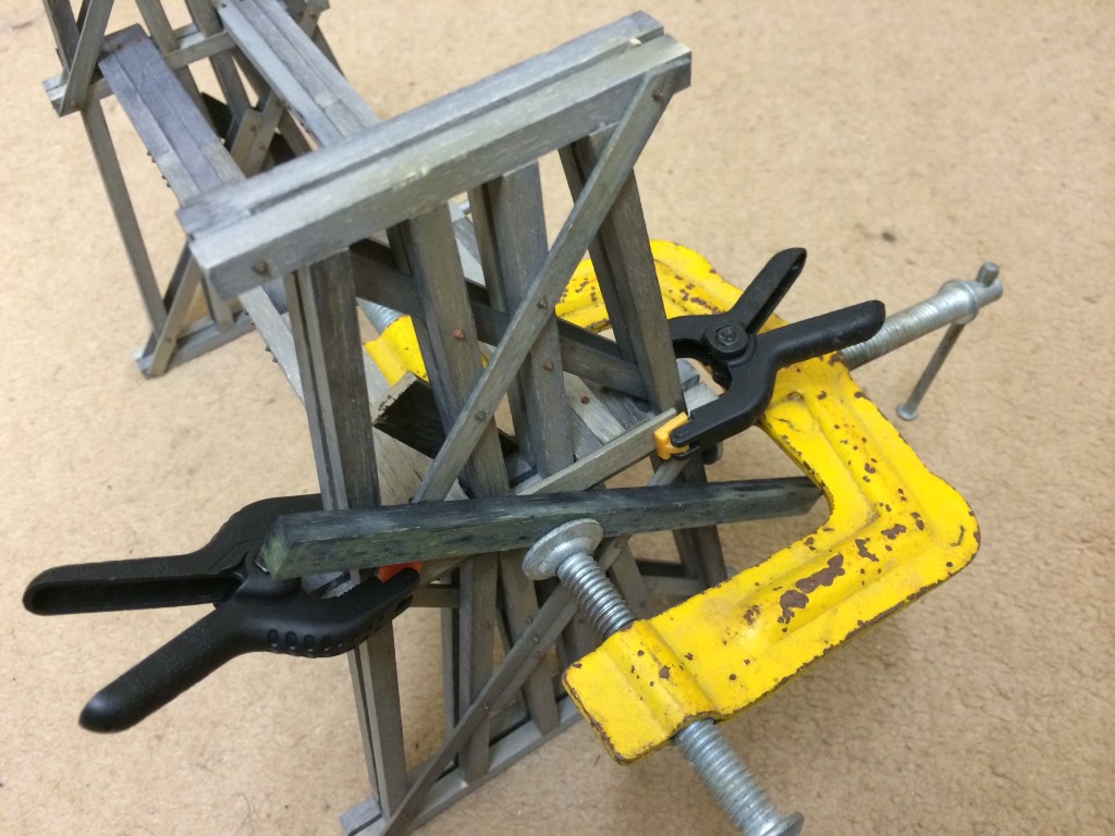
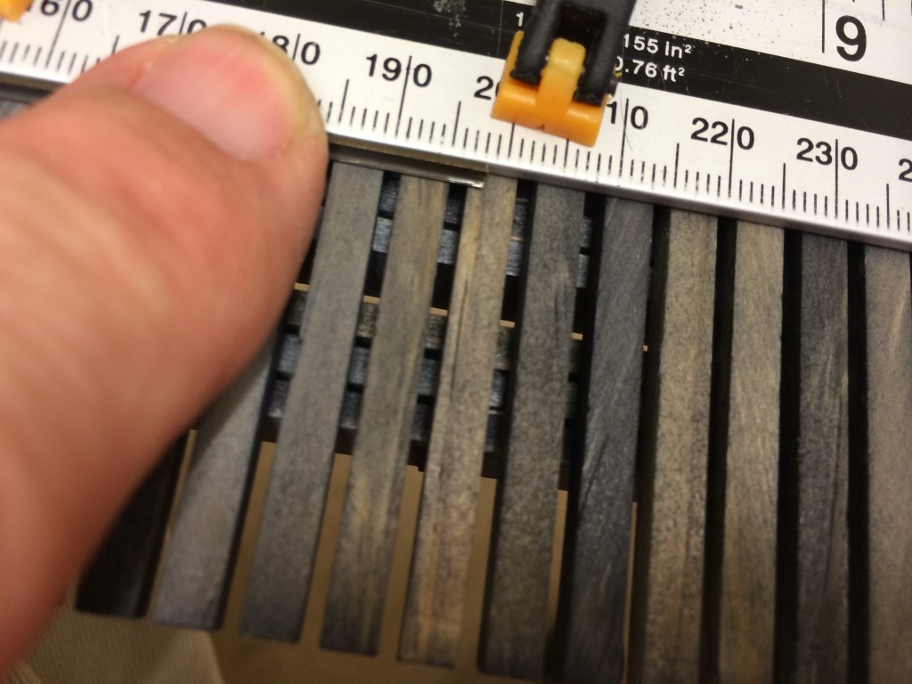
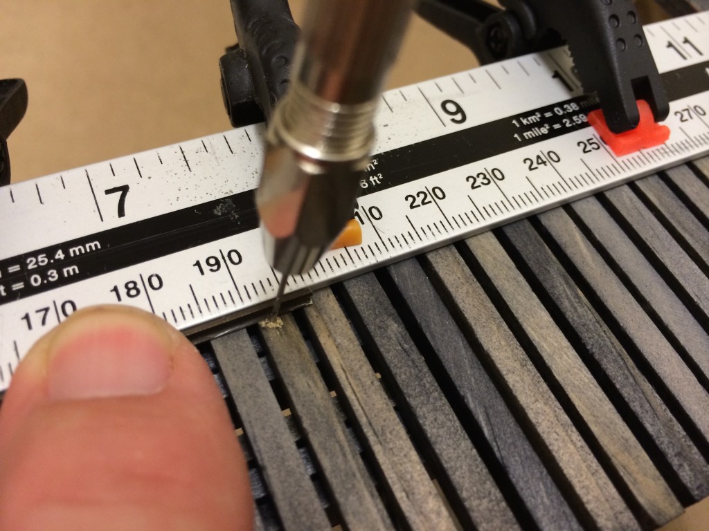
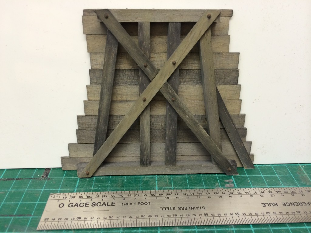
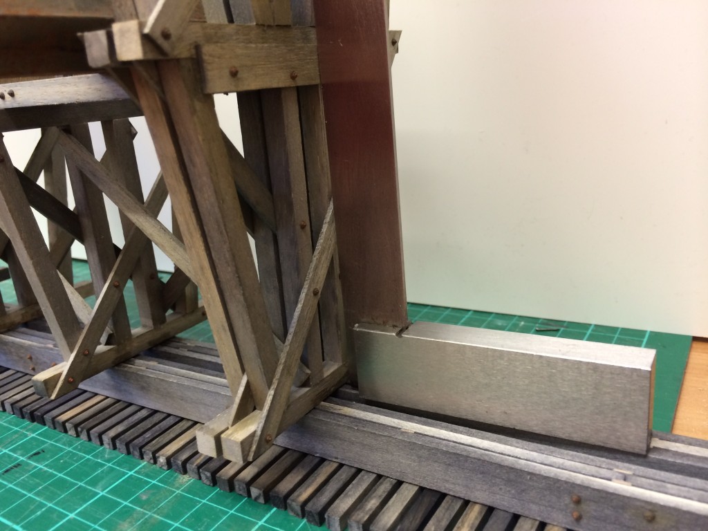
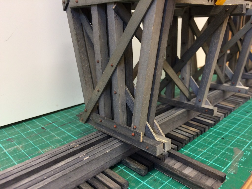
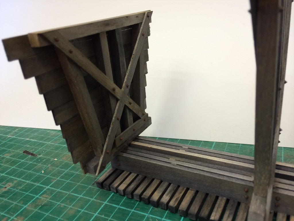
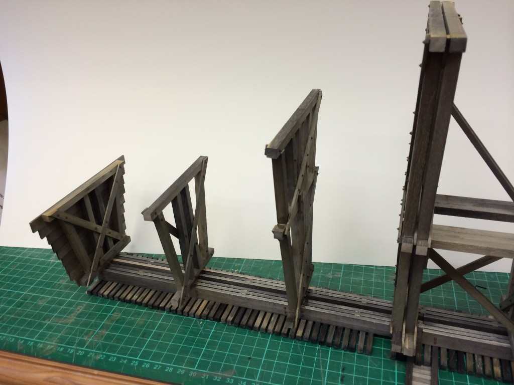
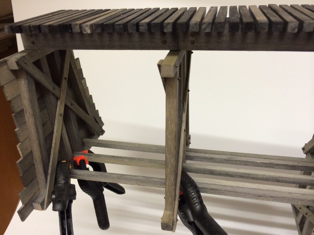
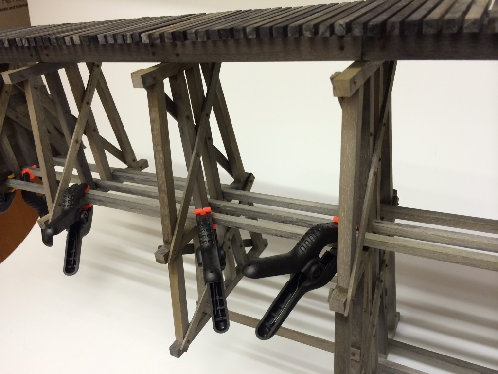
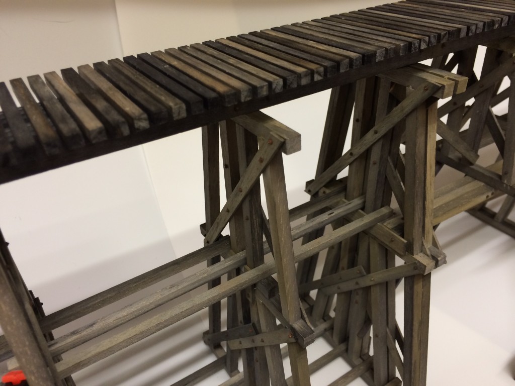
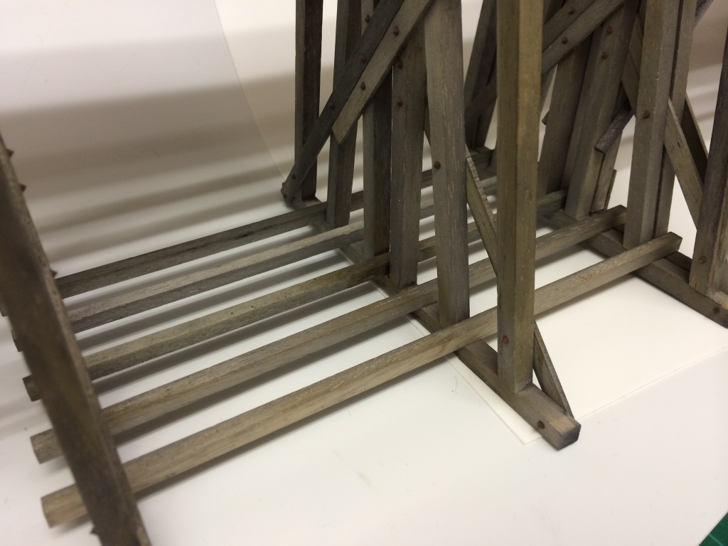
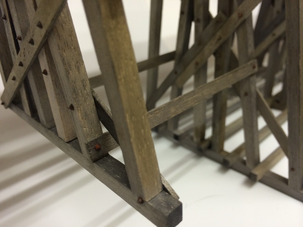
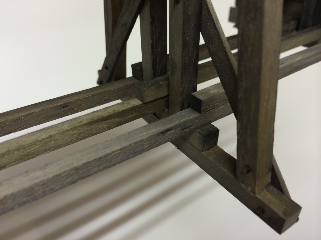
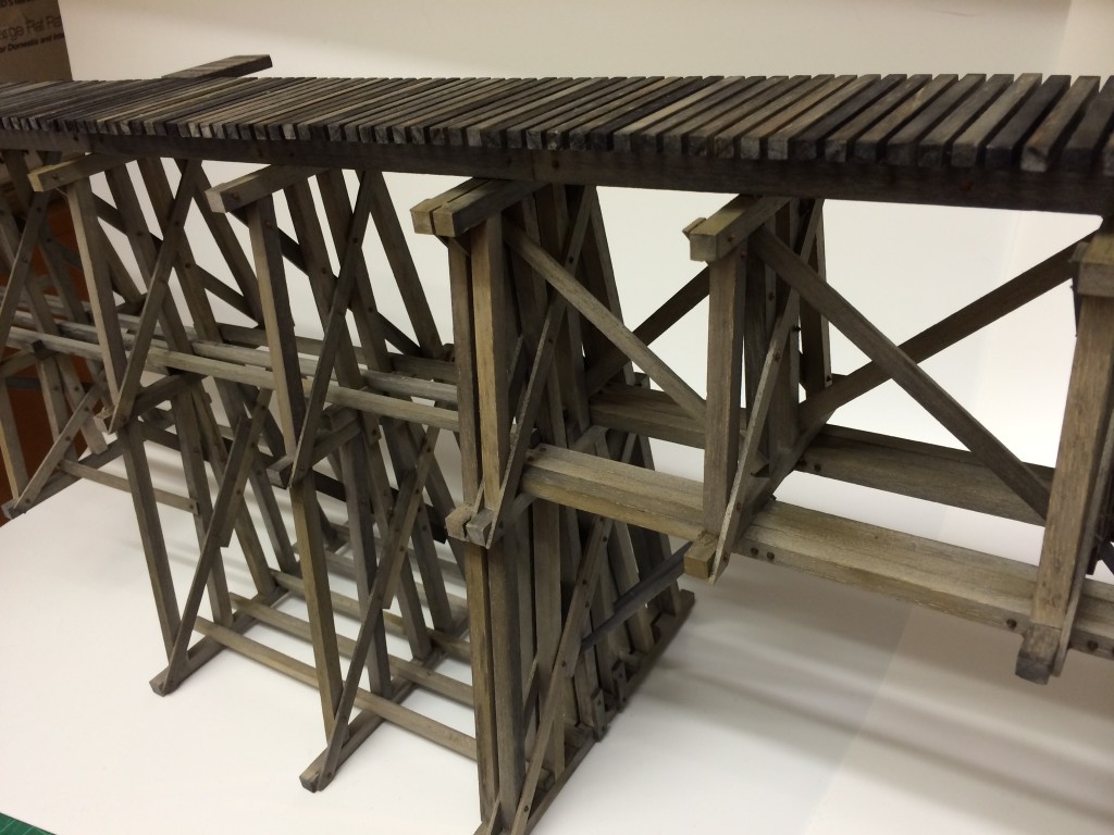
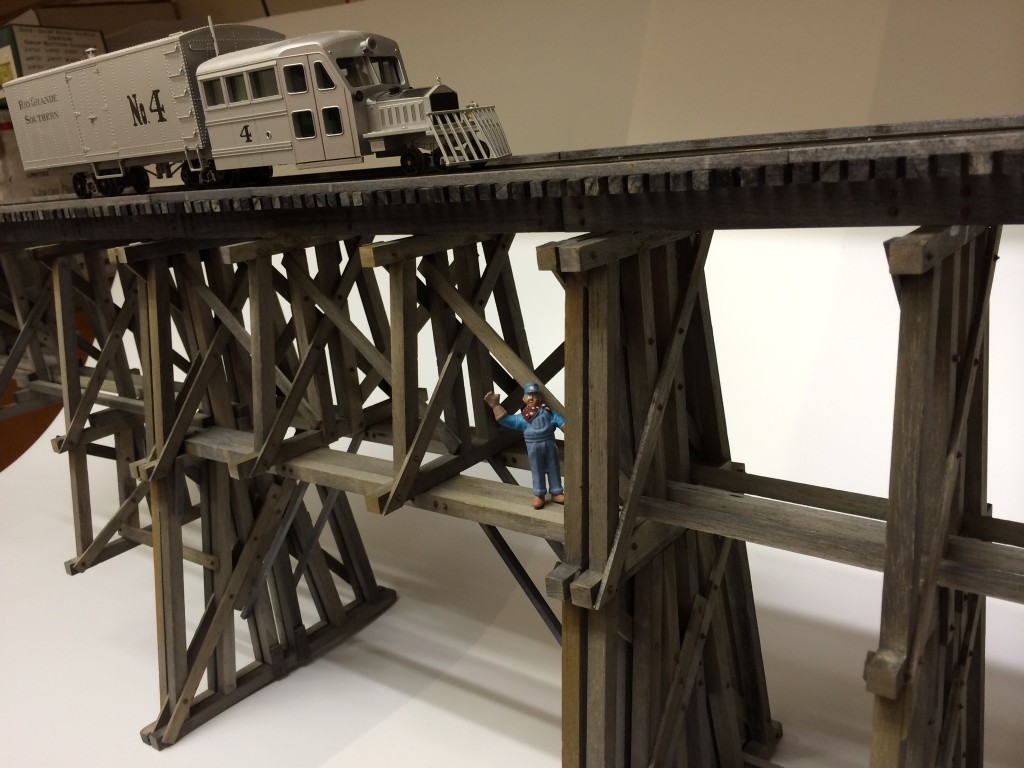
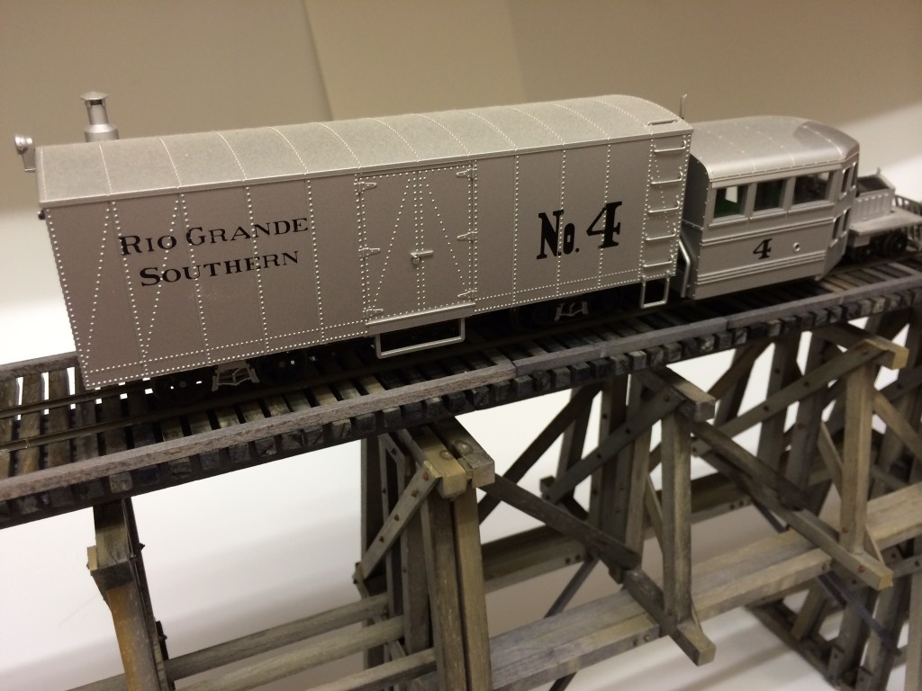
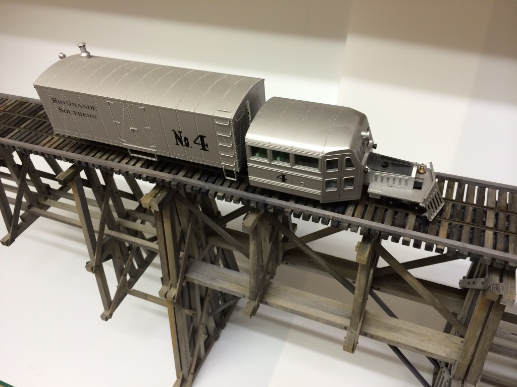
Strengthening the Trestle Structure with Cross Bracing
The photos below show the current progress with respect to strengthening the structure with cross bracing to support the weight of the bridge deck and ultimately heavy locomotives.
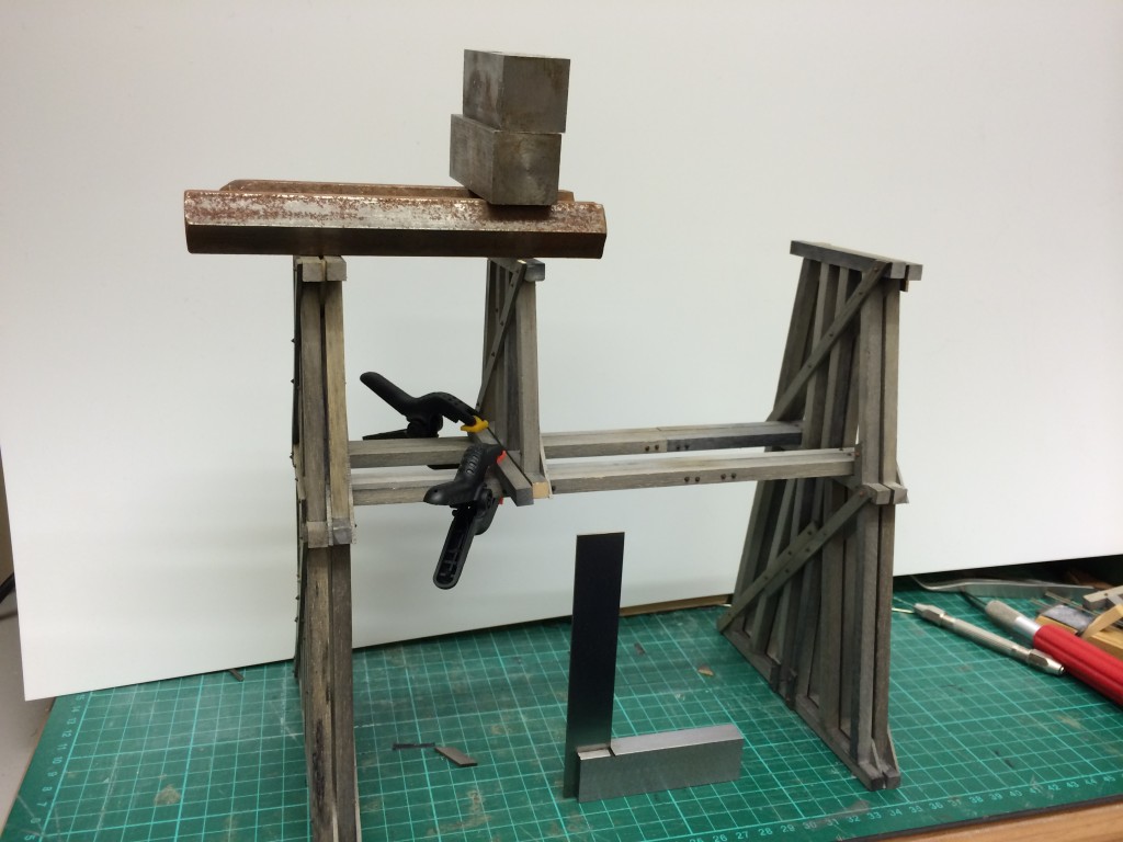
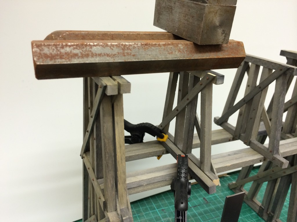
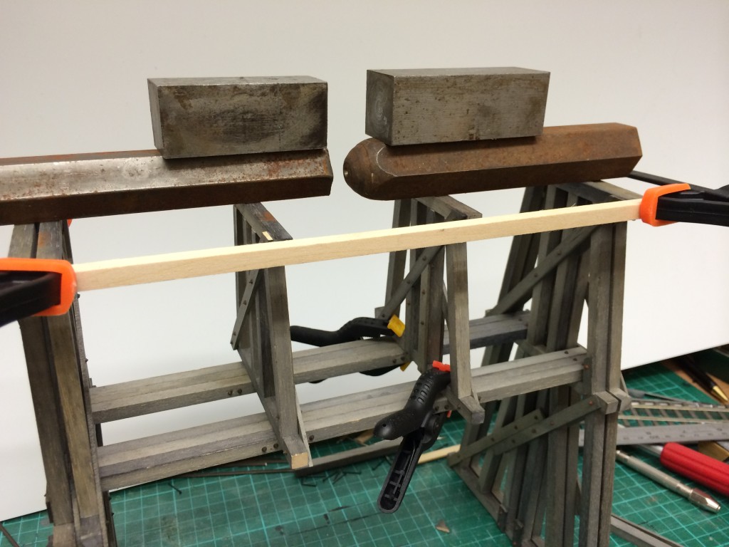
As the substructure starts coming together there is a distinct lack of rigidity in the overall structure and since this trestle bridge will eventually span a small valley the trestle bents will be attached to the ground surface but until that happens the structure needs reinforcing to allow it to be transported without its eventual base for display at shows and entering for competition and the achievement programme.
The following photos show the addition of cross bracing to "stiffen" up the structure.