
Page 9 - November December 2013
P. 9
Foam Board: some ideas and adventures in modular baseboard construction
After a lot of thought and planning, I’ve finally taken the plunge and started work on 16' of HO singletrack modular boards, called Quisling, using four 47 × 20 × 2.2 inch sections of pink foam board, purchased at B&Q. Whilst I’m sure others have constructed modules in this way before, it’s a departure for the club, and I’d like to share my progress. I’ve managed to get this far with some limited assistance from another club member, but I’ll need a lot more when the track and wiring fun starts to happen.
I’m using foam board as I want the module to be as lightweight as possible (I am, I find, not getting any younger . . .), and I’m wrapping them in plywood, to hopefully maintain the strength required to put up with the knockabout they will receive in regular use at the monthly Western Union club meet in Plymouth, to where they will be carried in my car from my home. Whilst the NMRA(BR) modular standard asks for 18" ends, my boards will remain at 20", the original width of the foam board; the single track at either end will be offset, to be the required 9" from one side, but 11" on the other.
Experience in examining (and carrying and transporting) others’ modules has also made me want to explore using integral legs, as separate legs seem to take up an inordinate amount of room in the car, and are always an additional hassle to load and unload. My ideas are very much a “work in progress”, and I continue to make a certain amount of it up as I go along, but I hope this ongoing account may be of use to others who are also contemplating building modules. If I can do it, you can, too.
Here’s the plan as envisaged: Quisling, a small township depot with a strong Southern Pacific flavour. It has a main line, passing loop, house track, and four sidings (team track, MoW siding, foodstuffs distribution, and a twotrack fruit packing facility).
As can also be seen, there will be some additional industry on the house track, nearest to the depot building. I’m using Peco Code 83 #8 switches on the main line, with #6 switches elsewhere (a total of 9). The above picture shows the tracks drawn, some rolling stock laid out, and some buildings placed in a few rough positions to give a notion of what can be realistically achieved in the available space, without overcrowding. There’s space on the main line at the RH end for a locomotive headshunt, should the boards be used as a terminus, although it’s a simple matter to build a 1' singletrack extender board to allow further flexibility in that role. At Western Union meets, we limit train lengths on “live ops” sessions to 10 cars, two Geeps and a caboose, and that length of train will fit comfortably into the loop at Quisling.
The foodstuffs distributor and fruit packing buildings will be scratchbuilt semiflats, backed and supported for strength by plywood extended upward from the board sides; once the buildings are ready to be attached, I will draw around them, and use a jigsaw to cut the plywood sides to the exact footprint of the backs of the buildings. The homesteads at top right will also have a plywood backing above the board edge for strength. As other modular boards at Western Union have 3" ends, and they seem to work well, I elected to have mine 3" too, using 9 mm marine ply. For the sides I used 6 mm marine ply, which I wanted to overlap the bottom of the foam board by an inch (to give space and protection for folding legs), and I also desired at least half an inch above all the boards, to take into account that the track level would be above the level of the foam, especially after it was placed on trackbed. The lip is also to protect the scenery at the board edge, and can be cut lower if required. As
Brian Moore
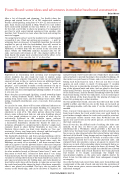
said previously, three board sides out of eight have much taller sides attached, to provide backing to the semiflat buildings. All the timber was purchased at Totem, and cut to size there too. Taking each foam board in turn, I first cut out four 15 mm squares on each corner, to insert 15 mmsquare 3" wooden blocks; they are to provide the strength, to facilitate the screw ing of the plywood ends and sides, and are glued to the foam board using NoNails, the tops being level with the top surface of the foam board, and the bottom extending below the lower foam board facing. On the two end pieces, I cut out some space on the bottom of the foam board for the placing of clamps to allow firm joiningup to other modules.
On this upsidedown board, also note that the track line in the middle is offset, and the two cuts in the foam are to match an 18' adjoining module, with the extra 2" on the LH side clearly marked.
Then, I cut out 15 mm spaces on the top level of each end of the foam board where the track would cross over each board, to give further strength where the track ends would be attached. 15 mmsquare timber inserts were then NoNailed into the spaces; one can be seen in the above picture, at the bottom of the black centreline.
Once all was dry, the difficult task of sticking the sides com menced. To do this, it’s best to get assistance, and to use something like a Workmate, which provides a flat base on which to lay the foam board upsidedown, whilst allowing you free access to glue plywood sides that extend below and above the level of the board. Using clamps and two lengths of wood, I then applied generous beads of NoNails to either side of the foam board, attached the 6 mm marine plywood sides, and clamped them into position, using a setsquare to ensure that there was an inch of ply extending above (eventually below, as the boards are inverted at this stage) the foam, all around. The ply sides were cut to a specific length that should have allowed an overlap at either end of each board for the 9 mm plywood end boards to fit snugly; annoyingly, the length was miscalculated slightly, so the sides were slightly shorter by about 5 mm, but this did not affect their subsequent strength or integrity.
Once the NoNails had cured, three holes were then drilled and countersunk at the end of each side and into the centreline of the 15 mm corner piece; screws were then inserted to provide additional strength.
december 2013 9
