
Page 11 - November December 2013
P. 11
Signals for the Cascade Division Jonathan Small Part 3 – The relays
When designing the signalling system, I’d decided that I would employ miniature relays. With toggle switches it is possible to display many of the required aspects, but not all. In particular I identified a need to display “all red”, and this required a level of switching I could only achieve with relays. More advanced circuitry employing logic gates would also work, no doubt, for those proficient with such electronics.
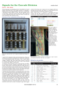
Overview of the construction of the relay case
Relay case, front view. The case is ready for installation and wiring in of signals
I used 12V DC miniature relays and mounting bases. These are commonlyavailable nonlatching relays, where the coil defaults to its closed position when the power is off. It opens when voltage is applied, and closes again when voltage is switched off. Unlike a solenoid motor, the coil of a relay is not damaged by voltage being applied continuously.
To make the relay operating circuits I experimented with differ ent mounting boards, including homemade printed circuit boards, using coppercoated board and ferric oxide solution to etch the circuit. In the end it proved to be just as efficient (and for me more reliable) simply to fix the relay bases to plain per forated board (without copper coating), and solder the various connections using fine insulated wire from below.
I designed the relay modules to accommodate up to four relays each, on equallysized boards and equallyspaced rows, to be mounted in a sturdy and accessible case that could be bench tested thoroughly before installation. Two “simple” modules could be mounted on one board, so there were nine modules to assemble. The mounting board needed some minor work to get the pins of the relay bases to fit through, then I glued these to the boards with Walthers Goo and clamped them overnight. The wiring of each module took under an hour, and once completed and tested, I mounted them in the relay case, and wired the leads into the series of terminal strips in the upper
section of the relay case. I made a test set of signals with con necting wires and relay test leads, so I could benchtest the whole thing before installation beneath the layout.
When wiring relays it is important to distinguish the two circuits: the one that controls the relays, from the signal control wires. Again I did this with rigorous colour coding:
To avoid conflicts I found it useful to have two different colours for the 12V DC+ signal feed. Note also that there is no 12V DC–, or common, connection to the signals in the relay case. There is one for the coils of the relays. A common return bus connects all the signals through their terminal blocks under the layout.
Rear view of relay module mounted in case. Here two “simple” modules are mounted on one base, two relays each module
Wiring the relay modules
The various boundaries on the layout are as follows:
Colour
Relay circuit
Signal circuit
Black
12vDC+ to relays
Blue
12vDC– to relays
Orange
12v DC + to signals 1
Purple
12v DC + to signals 2
Red
Red signal out
Green
Green signal out
Yellow
Yellow signal out
#
Relay Module
Block boundary
Module type
1
A
Interbay (yard) – W. Snohomish
Simple
2
B
Snohomish – Sno. Tunnel – Monroe
Compound B
3
C
Monroe – Sultan
Simple
4
E
Sultan – Gold Bar & Reiter
Junction E
5
D
Gold Bar – Index
Simple
6
F
Reiter & Index – Halford
Junction F
7
G
Halford – Baring
Simple
8
N
Halford – Snohomish Cut-off
Simple N
9
H
Baring – Grotto
Simple
10
J
Grotto – Skykomish
Simple
11
K
Skykomish – Scenic
Simple
12
L
Scenic – Cascade Tunnel – Berne
Compound L
13
M
Berne – Merritt
Simple
14
L
Merritt – Winton
Part of L
december 2013 11
