
Page 12 - November December 2013
P. 12
Let’s first take the case of what I’ve called a “simple” boundary – two signals controlling trains across the end of one block and its neighbour. A typical case is module K, at a location called Tonga, high above the Skykomish River gorge.
towns of Gold Bar and Index, diverging just west of Gold Bar and converging a short distance east of Index. This enables the scheduling of faster trains to pass locals a few times a day.
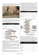
I decided to use a “dummy head” or extra aspect, yellow in this case, to indicate the train route being followed. So for the Sultan–Reiter/Gold Bar, served by “compound” module E, the required signal conditions are as follows. (A similar arrangement exists where the lines converge, at ReiterIndex/Halford, module F. These signals were pictured on the cover of the June edition of Roundhouse.) I designed a 4relay module to take care of this, using 2 DPDT and 2 4PDT relays. The relay positions and outputs are as follows:
Here is the wiring diagram for a compound module.
Signal
E Sultan
W Reiter
W Gold Bar
R1
R2
R3
R4
Default
R
R
R
C
E.bnd proceed Reiter
G
R
R
O
C
C
E.bnd proceed Gold Bar
G+Y
R
R
O
C
O
W.bnd Reiter–Sultan
R
G
R
O
O
C
W.bnd Gold Bar– Sultan
R
R
G
O
O
O
Westbound signal showing red aspect at Tonga
Here and at all the simple boundaries, the required conditions can be achieved using a pair of DPDT relays. These modules are identical. This table shows the signalling aspects and the state of the relays to achieve them.
C = closed (coil not fired); O = open (coil fired).
Here is the wiring diagram for all the simple modules, seen from beneath:
Signal at
West Scenic
East Skykomish
Relay 1
Relay 2
Default
R
R
C
Proceed westbound
G
R
O
C
Proceed eastbound
R
G
O
O
Following the diagram, and using Tonga as an example, we see that when relay 1 is closed, relay 2 does not come into play. Current flows from the orange (12V DC to signals in) to the two red signal connections.
When relay 1 is opened, connection is made to the middle (orange/purple) pair, and this carries the current to the input side of relay 2. When relay 2 is closed, current flows to green at West Scenic and red at East Skykomish, and when relay 2 is open, the opposite case applies.
This simple relay module is all that is required for twothirds of the signal sets on the railroad, and would serve for any case where a boundary between two singletrack blocks requires signalling.
More complex cases – junction signals
The two junctions (modules E & F) serve the part of the system where the main line bypasses the two neighbouring small
Special cases: A – Snohomish Tunnel block
This is a block between Snohomish Yard (Pacific Junction) and the town of Monroe. It is mostly in a tunnel, however, as the line passes through under the scenery to another part of the layout, out of view from the yard. Sno Tunnel block is used both for transit between towns, and also for switching access at either town. I decided to signal the two boundaries as one module, because of the need for both to be interlocked.
Signal
Pacific Jn
Sno. Tnl W
Sno. Tnl E
Monroe W
R1
R2
R3
R4
Default
R
R
R
R
C
Switching access from Sno.
G+Y
R
R
R
O
O
O
E-bnd proceed Sno.–Monroe
G
R
G
R
O
O
C
Switching access from Monroe
R
R
R
G+Y
O
C
O
W-bnd proceed Monroe–Sno.
R
G
R
G
O
C
C
12 rOUNdHOUSe
