
Page 13 - November December 2013
P. 13
Signal
Scenic
Berne
Winton
R1
R2
R3
Default
R
R
R
C
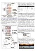
Special cases: B – Cascade Tunnel and Winton Tunnel
The final case is on the upper deck, reached through the Cascade Tunnel, a helix that climbs through five turns. The upper deck represents the railroad exiting the Cascade Tunnel at Berne, then passing eastward through Merritt and Winton, and entering the Winton Tunnel to continue eastwards. On the layout the line reenters the helix just beyond Winton, and after descending to the fourth level it rejoins the upward track, forming a return loop.
Signalling here needed some consideration. There are no signals inside the tunnel, so the signals at the entrances need to convey everything a train crew needs to know before entering. Therefore I designed a signalling module to take in the signals at Scenic (Cascade Tunnel west portal), Berne (east portal) and Winton Tunnel.
Once a train is in the tunnel, Tower Operator will set all signals to red (default) until it exits. Note that by the use of a long staging track in the helix (levels 1–3) it is possible to have a train arrive on the division from the east. Such trains exit from the Winton Tunnel, with all signals at red, and enter at Berne to descend through Cascade Tunnel with the signal there at green. (Crews can monitor the passage of trains through the tunnel by use of a control panel with LEDs to indicate the status of the return loop turnout, and a CCTV system.)
Construction of the relay case
The case you see in the photos has a solid frame and inner parts, to which the modules are mounted. Above them is a large space for terminal strips. I took care to ensure that there was room enough for fingers to reach in and insert wires! I made front and back dust covers from clear Perspex, the rear of which was fitted before the case was mounted under the layout. I connected the completed and tested case to the layout by running 4core and 8core cable from the master signal terminal panel into the case terminals. There were dozens of connections, it is true, but my method (while laborious) proved its worth: there were very few errors, and those that did occur were quickly located and fixed. I was careful to choose a location for the case that is easy to reach, in front and behind.
Controlling the signals – getting it all to work
Relays work by current being either absent (closed) or present (open). Controlling the simple module is easy enough. Here I use a DPDT centreoff toggle as shown below. The 12V DC+ feed is attached to both the central contacts. In the off position both relays stay closed. Throwing to connect to the lefthand contacts on the diagram will open the first relay. Thrown to connect to the right, it opens both.
I wired the various compound modules according to the diagram overleaf, with variants in the way they were connected. Again, the main component is a DPDT centreoff toggle. This time, when thrown to connect to the lefthand contacts it opens relay 1, and enables the operation of the SPST toggle shown on the left, which when closed will open relay 4. Throwing the DPDT to connect to the righthand contacts opens relays 1 and 2, and enables the SPST switch for relay 3.
The toggles are mounted in a control panel.
Eastbound enter at Scenic
G
R
R
O
C
Westbound enter at Berne
R
G
R
O
O
C
Eastbound enter at Winton
R
R
G
O
O
O
december 2013 13
