
Page 19 - NMRA Roundhouse March-April 2020
P. 19
AP MODELLING ARTICLE
A Freelance Steam Rail Motor
Eric Belshaw MMR Part 2
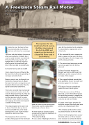
Six-Engined Sentinel Steam Locomotive, metre gauge for service in Colombia, South America from The Locomotive 14 July 1934, p198
I intend to cover the basics of two locomotive builds, one freelance and one scale based on a prototype.
I will start with the freelance locomotive, which was marked as a ‘Kitbash’, but it could so easily have been a scratch built if I had read the rules properly. I will highlight what I could have improved upon to get to the scratch-built goal, after I have described the build process.
So how did I end up with my model?
I had a chassis from an old Playcraft Bo- Bo diesel which offered the possibility of carrying a watertube boiler.
Deeper research into the Sentinel Loco showed the characteristics of a Beyer Garrett with a boiler carrying frame and headstock-fitted trucks rather than the typical head-stocked underframe.
The trucks contained what was basically a steam version of a traction motor. So, using the design parameter of a Shay, the steam traction motors of the Sentinel and the capacious body of the water tube boiler house, I defined a fictitious narrow-gauge locomotive and prepared a suitable working sketch.
The original engine had its water tank in front of the boiler, but my shorter version precluded that, so the design developed into a rear of cab mounted tank with a central coal chute.
The sloping body front would then provide a hiding space for the feed water
The inspiration for this model came from 2 sources, the Water tube boilered 4-6-4 of the LNER and research on the internet of a Steam Rail Motor used in South America.
heater, air reservoirs and the airpump. These items could be neatly hidden behind a pair of access doors.
My main departure from the original concept was to attach the headstocks to the body underframe
1. To make the Body
A. I cut a series of diaphragms from the
same 60 thou plasticard as the soleplate, 4 in all, profiled to replicate the curves of the boiler.
B.Two remained full size to support the boiler wrapper and two were cut down to provide support for the wrapper side and the sloping end plate.
C.The cab ends and sides were marked out and cut, again from the 60 thou plasticard.
D. One of the boiler wrapper dia- phragms was stuck to the forward cab bulkhead to provide a step to hold the rear edge of the wrapper.
E.The wrapper/bulkhead assembly had to be profiled to fit over the motor and provide a register for the chassis.
F The base of the rear cab bulkhead needed the same chassis register.
G. Cab sides were cut from 30 thou plasticard, as were the bulkhead gussets that would be necessary to support the rear bulkhead.The cut-out for the door made the cab side very flexible.
H. I made several paper templates for the Boiler wrapper, the sloping end plate and the rear mounted water tank.
I.The templates produced the continu- ous plasticard plates to skin the body.
J. Not all of the templates were success- ful initially and two or three attempts were necessary to achieve the desired
ROUNDHOUSE - March/April 2020
19
