
Page 15 - NMRA Roundhouse September October 2020
P. 15
internal width, which I strengthened
on each side with 3mm square styrene beams. I filed away some of the side parts of the RS3 split frame casting to
fit into a close-fitting locating hole cut in the chassis floor, and secured the mecha- nism using small screws. (The mechanism with its missing truck would otherwise no longer support the carbody, but would rather – and somewhat comically – fall out back end first...).
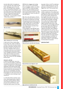
The new chasis
Chasis showing rear truck wiring
I made a pair of brass contact plates
for the rear truck, which I screwed to the floor.The screws had to be located precisely so that they could be reached between the wheels and side frame of the truck. I soldered contact wires to these plates inside the car and attached to the split frame where the manufac- turer’s headlight components are placed, using a piece of copper circuit strip. I later used the front headlight slot in a similar way to power the new headlights, front and rear.
Sidewalls and Ends
I had been wondering for some time how to solve the problem of replicating rivet heads and panel lines.These are es- sential to the appearance of heavyweight equipment, and smooth styrene simply doesn’t do the job, not even in N Scale. I had previously built some passenger and mail cars for my Cascadian train using wall sections cut from Rivarossi/Concor heavyweight cars with some success, and so I decided the same technique would suit this car.
I cut the sides off from the floor, some- times cutting longitudinally through the end wall to use the vestibule sections, and sometimes cutting across so as to preserve the end wall whole. I then sanded the walls smooth on the back.
X838 had four baggage-style loading doors, so for this car I used sections from two baggage-combine cars, enlarg- ing the windows to match prototype photos. I also used vestibule doors for the rear end.At the operating end the doors were inset by at least 6”, so I filed the moulded doors away and added my own inset doors.
After I’d cut the wall sections to fit the plans, the crucial step for the success of the model was to glue them accurately and squarely onto the chassis.To do this I took the height-above-rail by laying the model directly upon my scale drawing, and then fixing each section one at a time, taking extreme care that all was square and parallel.
On the engineer’s side X838 had three air intake vents for the engine compart- ment, which had louvered panels stand-
Body shell parts matched with drawing
ing proud of the car wall.To model these I took the ridged side grip out of a CD jewel case, cut the panels from this and edged them with 0.1mm styrene strips.
To replicate the curved front cab, for which no single piece of car-wall proved suitable, I first made a curved wall profile piece filed from thick styrene, then cut it into two parts above and below win- dow height. I then took sections of car wall and sanded the back to make them extremely thin and pliable, cementing them in place and clamping overnight
to ensure the right curvature. I then added individual window posts to get the windows the correct width, and used two-part epoxy filler (Fine Milliput) to fill around the edges and any gaps. 17 separate small pieces were needed for the front panel.The rear end was sim- pler, made from one styrene piece which I filed and sanded to shape, cut the door opening and then fitted and filled.At
this point I located the coupler bolsters using a Kadee gauge. I assembled the mechanism, temporarily screwing on MTL #1015 couplers to check and test the locomotive on my layout.
Jonathan Small
Body shell front and engineer’s side
Body shell rear and fireman’s side
ROUNDHOUSE - September/October 2020 - 75th Anniversary Issue
15
