
Page 21 - March April 2000
P. 21
CONSTRUCTOR’S CORNER...
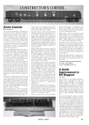
Aristo Gondola
Peter Prydderch
The conversion possibilities of this range of models interest me. Having knocked two boxcars into the double door version, it seemed logical to look at other types of vehicle. The Reefer will be a major job, as the roofs of the fifty footers did not have ice hatches... but, the left over ends from the boxcars will be used. So, a quick conversion was required. Fate brought me a Gondola in an auction. Luck provided another three of them on my third ‘phone call. The mould was set.
Firstly, after taking the trucks off, two of them were pulled apart. This is harder than it sounds. Tiny screws hold lugs by which the ends are attached. Even when unscrewed the screws have to be prised out. Then you have the floor joined to the two sides; three of the vertical pillars on the outside have inserts covering screws... ... the middle, and the ones next to the end ones. These can be prised off carefully, as they’ll need to go back. After the screws have been removed, the sides will need to be prised off. The floor has lugs on the sides, which fit into slots in the body. This is presumably why the body sides are so thick. Unfortunately they are glued in. Care and patience will provide four unbroken sides.
The greatest sensible length is from the end to the last stanchion before the body narrows again. When two of these lengths are joined, the new side will be a thou over fifty-one and a half feet - at 1/29th that is. For me, it seems reasonable to stick with the scale of the model, rather than try and adjust to 10mm or 1/32nd.
The vehicle that looks correct, is the home built Pennsy 52ft 6ins version - but with the stanchion spacing of the Bethlehem Steel B & O fifty-two and a half footer. See Train Shed Cyclopaedia Vol 5. Beyond that - no
clue! It was once suggested that these models were only representations anyway, and if it looks right, then it is right.
Two sides were cut on the inside of the far stanchion, with the other two being cut on the outside. Looking back this was a mistake. It would be better to cut down the middle of the stanchion. The rivet-heads on the inside will be well away from the join, and the join on the outside will be easier to fill. The ends were rubbed upon a piece of glasspaper upon a flat surface. You will find a sheet of toughened glass a godsend on your workbench.
When satisfied that they are as square as possible in two planes, join them together upon a flat surface. The solvent used was Chloroform, which is cheap and cheerful. It is also as dangerous as hell, and needs treating with respect in a well-ventilated non-smoking area. Several coats of the solvent to soften the edges, then pushing them together does the trick.
The next task is to decide what to do about the moulded handles on the inside that are used to anchor ropes. How about cutting the mouldings away with a chisel-blade Exacto, drilling holes on the insides of the housings, and making replacement, working, versions out of 0.7mm brass wire. Bend the wire over long-nose pliers...oh, you don’t need me to tell you how to make a top hat shape...then spring it into the holes. Spring is not quite the right word, as you’ll have to insert the pliers into the inside of the hat and prise it back into shape once in the holes... ...brass doesn’t spring back!
That leaves the middle ones to worry about. Due to the position of the cuts, only three brackets remain - simply leave the one on the rivet line, and cut the other two away. Then reposition one of them upon the other rivet line... it looks fine, honest!
Next cut the two floors to fit the length,
but not in the middle - to avoid all the joins being in the middle of the vehicle. Glue these together. The screw holes will still be correct for attaching the sides.
That’s it then... throw some paint on, and all that remains is to re-assemble the sides, ends, and the floor. The handrails were replaced with 0.8mm brass wire - they look better. Finally apply any touching up necessary, and then apply the lettering.
The trucks can be used as they are, or insert metal wheels for better running and looks. The frames were made narrower to reduce the side-play built into them. This is achieved by removing a few millimetres from the stretchers. More of that again... oh, just do it! Chloroform was again used as the adhesive.
My model was painted to represent a Norfolk and Western vehicle, though such a prototype never operated under the N & W banner.
If anyone wants more information:
fax + 44 161 439 4849 e-mail ppltd@hotmail.com
A Quick
Improvement to
HO Hoppers
The Editor
We’ve read a lot about improving plastic freight cars, especially box cars, by replacing steps and grabs. The standard plastic hopper cars have a still bigger aesthetic problem, caused by the horizontal bracing bars found at the corners. In some makes, these are represented by thick plastic ‘ledges’ but are supposed to be quite slim rods, or tubes possibly, rather like the size of diesel handrails. (Fig 1 on page 22)
It is also true that the columns of hand- grabs forming ladders at some corners of the car are quite heavy, and although I have done one or two replacement jobs for those, it is quite a marathon to replace all those grabs, especially as the vertical steel “angle-iron” forming the car corner has to take grabs both from the end and the side of the car, making the hole-drilling process very difficult and often causing the plastic to break up. On one such car I got around this by drilling holes only for the end grabs, while the ‘outer’ ends of the side grabs were just cemented flat to the angle iron. This seems to have worked so far!
APRIL 2000 21
