
Page 17 - B2B 8 to 13
P. 17
Back2Basics
PART 11 – USING ELECTRICAL METERS
By John Firth
From discussions with a number of fellow members at a Convention it was clear that some members are unsure how to use electrical meters. They are such a useful item to have around the layout, not only during construction but also during operating sessions when things start to go wrong.....
Introduction to Electrical Meters
There are a number of things that need to be measured in an electrical circuit, the most common being current, voltage and resistance. What are these?
Current is the flow of electricity, effectively the number of electrons passing a particular point in a particular time. It is measured in Amperes but commonly referred to as Amps.
Voltage is the measure of the electrical force causing electrons to flow around the circuit. It is measured in Volts.
Resistance is a measure of the obstruction to current flow in the circuit. It is measured in Ohms. The more resistance there is in a circuit, the greater the voltage required to cause a particular current to flow. The famous formula known as Ohms Law that links resistance (R), current (A) and voltage (V) is
R=V÷A
So 10 volts applied across a resistance of 100 ohms will produce a current of 1/10 amps or 0.1 amps. The symbol for ohms is Ω.
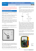
Until 20 years ago, most meters were analogue meters similar to the one shown below (Fig 1).
Fig 1
The basic analogue meter is really a current measuring device. To measure voltage, a high resistance is inserted in series with the meter. It measures the voltage by measuring the current that the voltage causes to flow through the meter.
Analogue meters have an advantage in that they can be read at a glance. They are particularly good as panel meters where it is important to be able to quickly assess the state of a circuit. They
can also help in identifying rapid fluctuations in the circuit because the needle can move rapidly following a change of current or voltage.
A basic meter can lead to inaccuracies in readings. This arises not only because of difficulty of reading the value from the meter position, but due to the relatively low resistance of the device. In many cases this is not a problem, but it can be misleading.
10 V
1MΩ
1MΩ
V 1MΩ
Fig 2
In this circuit (Fig 2) we have 2 resistors of 1 megohms (1,000,000 ohms) in series with a voltage of 10 volts across the pair. There would be 5 volts across each. We then put a voltmeter with a resistance of 1 megohms across one of the resistors. It will indicate a voltage of 3.3 volts. The reading is accurate in that it measures the voltage there when the meter is in circuit, but putting the meter there has changed the voltage being measured from what it was before the meter was present. This was a problem with basic analogue voltmeters because there was a limit to the resistance that could be built into them as the energy they required to operate had to come from the circuit they were measuring.
The term “multimeter” is used to identify a meter that can be switched to read voltage, current or resistance (and sometimes additional functions.
There are some analogue multimeters (Fig 3) which overcome the problem of low resistance by having a battery power supply and an amplifier. This increases the resistance of the voltmeter so that it has less affect on the circuit being measured.
Fig 3
Example of an analogue multimeter
February 2018 - ROUNDHOUSE 15
