
Page 18 - B2B 8 to 13
P. 18
The alternative to the analogue meter is the digital meter. This always has a separate power supply in the form of a battery and displays the reading in digital form. It is more accurate than an analogue meter because the reading can be read off without needing to interpolate between marks and, like the battery powered analogue meter, it can have far less affect on the circuit being measured because it can be a much higher resistance. Unlike when digital meters first appeared, they are now cheaper than analogue meters. Because they use an internal battery, do remember to switch them off when not in use.
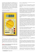
I am going to select a simple digital multimeter for general purpose testing. This one costs under £5.
Fig 4
This meter allows you to measure d.c. voltages from a few millivolts (thousandths of a volt) up to 600 volts and d.c currents from a few microamps (millionths of an amp) up to 10 amps. Measurement of a.c. is more restricted. It will measure a.c. voltages up to 600 volts but with less precision than d.c. voltages. This one does not allow measurement of a.c. currents but some do.
WARNING: Be very careful when measuring voltages above about 100 volts as these can be lethal.
The multi-position switch rotates through various sections. One section is labelled V This is the section for measuring d.c. voltage. On this particular meter the available ranges are 500, 200, 20, 2000m, and 200m. These correspond to 500 volts, 200 volts, 20 volts, 2000 millivolts (or 2 volts) and 200 millivolts (0.2
volts). If it is used to measure a 1.5 volt battery, then the ideal scale to select is 2000m (or 2 volt).
Generally digital meters are not worried by polarity. If the Red (positive) lead is connected to the negative of the supply, the reading will give the correct numeric value but preceded by a minus sign.
If the 500 range is selected, the battery will give a reading of 002 meaning more than 1 volt but less than 2. The 200 range gives a more accurate figure of 01.5 meaning approximately 1.5 volts. Using the 20 range gives a better accuracy of maybe 1.59. Using the 2000m range gives the best result of maybe 1.598. Going to the 200m range gives a reading of 1. This means that the voltage it is measuring is greater than 200 millivolts. Overloading the meter in this way will not normally cause it any damage.
The section labelled V is for measuring a.c. voltages. This meter only has 500 and 200 ranges so if it is used to measure 16 volts a.c., then the 200 range should be used. The result would not be particularly accurate but it is a reasonable indication of the voltage.
The next section for consideration is labelled A . This is the d.c. current range. The meter has 3 input sockets labelled COM, VΩmA and 10A. Measurements using the 2000μ (2000 micro amps), 20m (20 milliamps) and 200m (200 milliamps) ranges use the VΩmA and COM terminals. This meter is fused so that if a greater current than 200 milliamps flows, an internal fuse blows and will need replacing. The other current range labelled 10A uses to 10A and COM terminals. Again, it has an internal fuse. Be careful when using this range. Remember to put the leads back in the correct position afterwards as trying to measure a voltage via the 10A socket can do significant damage to the meter, the equipment being tested and to YOU.
This meter does not have the capability of measuring a.c. current, but this is what you should expect from a meter which is cheap enough to be given away with a box of cornflakes!
Finally we come to the resistance scale. This meter has ranges 2000k, 200k, 20k, 2000 and 200. The 2000k range is for measuring resistance up to 2 MegOhms (2 million ohms). Be careful not to touch the terminals when using this range as it will give a reading of your resistance, making your readings inaccurate. The 2000 ohm range shows a diode. This is probably the best range for checking whether a semiconductor diode is working or not. The 200 ohm range includes a buzzer. If the resistance being measured is very low, as well as giving a reading, it buzzes so that you can confirm continuity without having to read the scale.
There is one last position labelled hFE. This is associated with measuring the amplification of a transistor. I suspect this is very rarely used.
Unlike the basic analogue voltmeter previously described, the digital meter is likely to have a much higher internal resistance so it is much less likely to alter the voltage being read. In the circuit above (Fig 2), it is likely to indicate 5 volts as it does not “load” the circuit.
It can measure resistance. It does this by using its internal battery to drive a small current through the circuit under test. It measures the current that manages to flow as a result of this internal battery and displays this as the resistance in ohms that this represents.
It measures resistance from a few ohms up to 2 megohms. On the 2 megohm scale, it will indicate the resistance of your body if you hold the terminals. Care therefore has to be taken when
16 ROUNDHOUSE - February 2018
