
Page 19 - B2B 8 to 13
P. 19
measuring very high resistance that you do not inadvertently measure your own resistance.
A useful feature provided by this meter is that it has an internal sounder that makes an audible tone when a low resistance path exists between the terminals. This is useful when checking continuity without having to look at the meter to see whether there is a reading.
The meter provides a means of testing transistors but this is a feature that few will use.
There is an issue with measuring alternating current (a.c.) The meter gives a reading that assumes that the waveform is a “sine” wave. If it has a different waveform (such as is encountered in DCC) then the value it gives will not be a “true” reading but it will be good enough for many purposes.
Finally, it is worth discussing to 10 amp range. Most readings involve having the test leads plugged into the normal terminals. However, to measure 10 amps requires one lead to be moved into a special 10 amp socket. This introduces a danger. If this socket has been used and the lead is left in this position, there will be a near short circuit between the leads. If you try to measure a voltage with the leads in this position, it can damage the meter, the equipment under test and YOU!!
So how do you use a meter?
Voltage is probably the most useful thing to measure. Your loco has just come to an abrupt halt. The voltmeter will tell you whether there is voltage on the rails. If you are operating D.C., then you will use a D.C. range on the meter. For DCC, the voltage is A.C. so you will need to use an A.C. range.
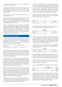
abcdef a1 b1 c1 d1 e1 f1
To illustrate fault finding with a meter, here is a simple example. The layout consist of 3 modules connected by jumpers. There is a break in a rail shown by the red cross. Now this is likely to be found by noticing that this is where the loco stops, and a meter may not be necessary, but the example shows how to locate the problem with a meter logically.
Putting the meter on the correct range for the power supply (D.C. or A.C.), test the output terminals of the power supply. Make sure that there is a reading here. If there is not, disconnect the power supply from the track and test again. If the fault was a short circuit somewhere on the track, the voltage on the power supply output terminals could be zero because of the short and the voltage would be present once the short was removed.
Next, test for voltage at intervals across the rails at b/b1, c/c1, d/d1 and so on. In the case of our fault, we will have a voltage across the rails at d/d1 but nothing at e/e1. We would then move back until we found where it disappeared. So we have a voltage between d and d1 and not between e and e1. But which rail has the break? By testing between d and e1 we will have a voltage and between e and e1 we do not. This shows that the break is between d and e rather than between d1 and e1.
Unfortunately, if it is not a clean break but a high resistance, it is not that simple as the meter will show a voltage across the track at e/e1 because the resistance of the meter is much greater than the resistance of the break but a loco will not work there.
Another way of finding the fault is by using the Resistance feature of the meter. Use the 200Ω range with the power supply turned off. You can then test between a and b, then a1 to b1, then b and c, b1 to c1 and so on. If there is continuity, the meter will read between zero and a couple of ohms. If the meter reads “1” with no zeros displayed, then this means a higher value of resistance than the meter is set to read, in this case 200Ω. If the reading is more than 3 or 4 Ω, then the reason needs to be investigated.
Now let’s use the meter to measure current. I will use the modular example again, but the rail break has been fixed. There is a loco L1 on the third section which can draw current.
L1
The ammeter has to be put into the circuit. In this example it can be put in place of any of the jumpers between modules.
A
L1
I have put the ammeter in place of the jumper between Module 1 and 2. The chosen meter does not measure A.C. current so this will only work for D.C. As the current is likely to be more than 200 milliamps (0.2 A) the leads are in the 10A and Common positions on the meter and the meter is set to 10A. It will now measure the current flowing in the circuit through the loco.
In the above example it does not matter at which jumper the meter is inserted. It will give the same current reading wherever it
Power Supply
Power Supply
Power Supply
is placed in the circuit.
L2
A
Power Supply
L1
If we now introduce a second loco L2 and leave the meter where it was, the ammeter only measures the current drawn by loco L1. To measure the current drawn by both locos, the meter has to be inserted at one of the two jumpers adjacent to the power supply.
We used the meter to identify a high resistance rail joint, but it is difficult to identify resistance of 2 ohms or less, but this can produce some problems to operation.
I use an old car headlight bulb in conjunction with the meter for this.
V
Lamp
I adjust the power supply to deliver about 1⁄2 amp. I then use the voltmeter to test across each rail-joiner looking for those with a higher voltage across them. If the joint has a resistance of 0.1 ohms, with 1⁄2 amp flowing, then a voltage of 0.05 volts (or 50 millivolts) can be measured across the joint. The resistance ranges of the meter would not detect a resistance as low as this, but it is easily measured with the voltage range of the meter.
Power Supply
February 2018 - ROUNDHOUSE 17
